USB Connectors and plugs
 |
Connectors properties
Usability and orientation
The connectors the USB committee specifies support a number of USB's underlying goals, and reflect lessons learned from the many connectors the computer industry has used. The connector mounted on the host or device is called the receptacle, and the connector attached to the cable is called the plug. The standard purposely defines this to prevent the use of extension cables.The official USB specification documents also periodically define the term male to represent the plug, and female to represent the receptacle.
By design, it is difficult to insert a USB plug into its receptacle incorrectly. The USB specification states that the required USB icon must be embossed on the "topside" of the USB plug, which "...provides easy user recognition and facilitates alignment during the mating process." The specification also shows that the "recommended" "Manufacturer's logo" ("engraved" on the diagram but not specified in the text) is on the opposite side of the USB icon. The specification further states, "The USB Icon is also located adjacent to each receptacle. Receptacles should be oriented to allow the icon on the plug to be visible during the mating process." However, the specification does not consider the height of the device compared to the eye level height of the user, so the side of the cable that is "visible" when mated to a computer on a desk can depend on whether the user is standing or kneeling.
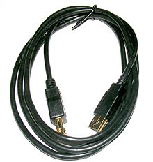
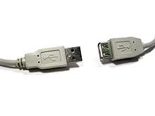
USB extension cord
While it would have been better for usability if the cable could be plugged in with either side up, the original design left this out to make manufacturing as inexpensive as possible. Ajay Bhatt, who was involved in the original USB design team, is working on a new design to make the cable insertable either side up. The new reversible plug is also much smaller than the current USB 3.0 Micro-B connector. It is called Type-C, and should be introduced as an addition to the existing USB 3.1 specification.
Only moderate force is needed to insert or remove a USB cable. USB cables and small USB devices are held in place by the gripping force from the receptacle (without need of the screws, clips, or thumb-turns other connectors have required).
Power-use topology
The standard connectors were deliberately intended to enforce the directed topology of a USB network: type A connectors on host devices that supply power and type B connectors on target devices that draw power. This is intended to prevent users from accidentally connecting two USB power supplies to each other, which could lead to short circuits and dangerously high currents, circuit failures, or even fire. USB does not support cyclic networks and the standard connectors from incompatible USB devices are themselves incompatible.
However, some of this directed topology is lost with the advent of multi-purpose USB connections (such as USB On-The-Go in smartphones, and USB-powered Wi-Fi routers), which require A-to-A, B-to-B, and sometimes Y/splitter cables. See the USB On-The-Go connectors section below, for a more detailed summary description.
Durability
The standard connectors were designed to be robust. Because USB is hot-pluggable, the connectors would be used more frequently, and perhaps with less care, than other connectors. Many previous connector designs were fragile, specifying embedded component pins or other delicate parts that were vulnerable to bending or breaking. The electrical contacts in a USB connector are protected by an adjacent plastic tongue, and the entire connecting assembly is usually protected by an enclosing metal sheath.
The connector construction always ensures that the external sheath on the plug makes contact with its counterpart in the receptacle before any of the four connectors within make electrical contact. The external metallic sheath is typically connected to system ground, thus dissipating damaging static charges. This enclosure design also provides a degree of protection from electromagnetic interference to the USB signal while it travels through the mated connector pair (the only location when the otherwise twisted data pairtravels in parallel). In addition, because of the required sizes of the power and common connections, they are made after the system ground but before the data connections. This type of staged make-break timing allows for electrically safe hot-swapping.[41]
The newer Micro-USB receptacles are designed for up to 10,000 cycles of insertion and removal between the receptacle and plug, compared to 1,500 for the standard USB and 5,000 for the Mini-USB receptacle. This is accomplished by adding a locking device and by moving the leaf-spring connector from the jack to the plug, so that the most-stressed part is on the cable side of the connection. This change was made so that the connector on the less expensive cable would bear the most wear instead of the more expensive micro-USB device.
Compatibility
The USB standard specifies relatively loose tolerances for compliant USB connectors to minimize physical incompatibilities in connectors from different vendors. To address a weakness present in some other connector standards, the USB specification also defines limits to the size of a connecting device in the area around its plug. This was done to prevent a device from blocking adjacent ports due to the size of the cable strain relief mechanism (usually molding integral with the cable outer insulation) at the connector. Compliant devices must either fit within the size restrictions or support a compliant extension cable that does.
In general, cables have only plugs, and hosts and devices have only receptacles. Hosts almost universally have type-A receptacles, and devices one or another type-B variety. Type-A plugs mate only with type-A receptacles, and type-B with type-B; they are deliberately physically incompatible. However, an extension to USB standard specification calledUSB On-The-Go allows a single port to act as either a host or a device—chosen by which end of the cable plugs into the receptacle on the unit. Even after the cable is hooked up and the units are communicating, the two units may "swap" ends under program control. This capability is meant for units such as PDAs in which the USB link might connect to a PC's host port as a device in one instance, yet connect as a host itself to a keyboard and mouse device in another instance.
USB 3.0 connectors
Main article: USB 3.0 backward compatibility
Type A plugs and receptacles from both USB 3.0 and USB 2.0 are designed to interoperate. Type B plugs and receptacles in USB 3.0 are somewhat larger than those in USB 2.0; thus, USB 2.0 Type B plugs can fit into USB 3.0 Type B receptacles, while the opposite is not possible.
Connectors types
Types of USB connectors left to right (ruler in centimeters): Micro-B plug, UC-E6 proprietary (non-USB) plug, Mini-B plug, Standard-A receptacle (upside down), Standard-A plug, Standard-B plug
There are several types of USB connectors, including some that have been added while the specification progressed. The original USB specification detailed Standard-A and Standard-B plugs and receptacles; the B connector was necessary so that cabling could be plug ended at both ends and still prevent users from connecting one computer receptacle to another. The first engineering change notice to the USB 2.0 specification added Mini-B plugs and receptacles.

Types of USB connectors left to right (ruler in centimeters): Micro-B plug, UC-E6 proprietary (non-USB) plug, Mini-B plug, Standard-A receptacle (upside down), Standard-A plug, Standard-B plug
The data connectors in the Standard-A plug are actually recessed in the plug as compared to the outside power connectors. This permits the power to connect first, which prevents data errors by allowing the device to power up first and then transfer the data. Some devices operate in different modes depending on whether the data connection is made. This difference in connection can be exploited by inserting the connector only partially. For example, some battery-powered MP3 players switch into file transfer mode and cannot play MP3 files while a USB plug is fully inserted, but can be operated in MP3 playback mode using USB power by inserting the plug only part way so that the power slots make contact while the data slots do not. This enables those devices to be operated in MP3 playback mode while getting power from the cable.
To reliably enable a charge-only feature, modern USB accessory peripherals now include charging cables that provide power connections to the host port but no data connections, and both home and vehicle charging docks are available that supply power from a converter device and do not include a host device and data pins, allowing any capable USB device to charge or operate from a standard USB cable.
Standard connectors
Pin configuration of the USB connectors Standard A/B, viewed looking into face/end of plug
The USB 2.0 Standard-A type of USB plug is a flattened rectangle that inserts into a "downstream-port" receptacle on the USB host, or a hub, and carries both power and data. This plug is frequently seen on cables that are permanently attached to a device, such as one connecting a keyboard or mouse to the computer via USB connection.
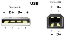 |
Pin configuration of the USB connectors Standard A/B, viewed looking into face/end of plug
USB connections eventually wear out as the connection loosens through repeated plugging and unplugging. The lifetime of a USB-A male connector is approximately 1,500 connect/disconnect cycles.
A Standard-B plug—which has a square shape with beveled exterior corners—typically plugs into an "upstream receptacle" on a device that uses a removable cable, e.g., a printer. On some devices, the Type B receptacle has no data connections, being used solely for accepting power from the upstream device. This two-connector-type scheme (A/B) prevents a user from accidentally creating an electrical loop.
Mini and Micro connectors
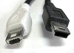
USB Mini A (left) and USB Mini B (right) plugs
Various connectors have been used for smaller devices such as digital cameras, smartphones, and tablet computers. These include the now-deprecated (i.e. de-certified but standardized) Mini-A and Mini-AB connectors (Mini-B connectors are still supported but not OTG (On The Go, i.e. mobile) compliant).[45] The Mini-B USB connector was standard for transferring data to and from the early data phones and PDAs, such as Blackberrys.
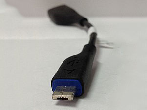
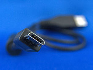
The Mini-A and Mini-B plugs are approximately 3 by 7 mm. The micro-USB plugs have a similar width and approximately half the thickness, enabling their integration into thinner portable devices. The micro-A connector is 6.85 by 1.8 mm with a maximum overmold size of 11.7 by 8.5 mm. The micro-B connector is 6.85 by 1.8 mm with a maximum overmold size of 10.6 by 8.5 mm.
The Micro-USB connector was announced by the USB-IF on 4 January 2007.The Micro B USB connector has a maximum current rating of either 1 A per pin, or 1.8 A for pins 1 and 5, and 0.5 A for pins 2, 3, and 4. The Mini-A connector and the Mini-AB receptacle connector were deprecated on 23 May 2007. While many currently available devices and cables still use Mini plugs, the newer Micro connectors are being widely adopted and as of December 2010, they are the most widely used. The thinner micro connectors are intended to replace the Mini plugs in new devices including smartphones, personal digital assistants, and cameras.The Micro plug design is rated for at least 10,000 connect-disconnect cycles—significantly more than the Mini plug design. It is also designed to reduce the mechanical wear on the device; instead the easier-to-replace cable is designed to bear the mechanical wear of connection and disconnection. The Universal Serial Bus Micro-USB Cables and Connectors Specification details the mechanical characteristics of Micro-A plugs, Micro-AB receptacles (which accept both Micro-A and Micro-B plugs), and Micro-B plugs and receptacles, along with a Standard-A receptacle to Micro-A plug adapter.
The cellular phone carrier group, Open Mobile Terminal Platform (OMTP) in 2007 endorsed Micro-USB as the standard connector for data and power on mobile devices In addition, on 22 October 2009 the International Telecommunication Union (ITU) has also announced that it had embraced micro-USB as the Universal Charging Solution its "energy-efficient one-charger-fits-all new mobile phone solution", and added: "Based on the Micro-USB interface, UCS chargers also include a 4-star or higher efficiency rating—up to three times more energy-efficient than an unrated charger."
The European Standardisation Bodies CEN, CENELEC and ETSI (independent of the OMTP/GSMA proposal) defined a common External Power Supply (EPS) for use with smartphones sold in the EU based on micro-USB.14 of the world's largest mobile phone manufacturers signed the EU's common EPS Memorandum of Understanding (MoU). Apple Inc., one of the original MoU signers, makes micro-USB adapters available – as permitted in the Common EPS MoU – for its iPhones equipped with Apple's proprietary 30 pin dock connector or (later) "Lightning" connector.
USB On-The-Go connectors
Main article: USB On-The-Go
All current USB On-The-Go (OTG) devices are required to have one, and only one USB connector: a Micro-AB receptacle. This receptacle is capable of accepting both Micro-A and Micro-B plugs, attached to any of the legal cables and adapters as defined in Micro-USB1.01. Prior to the development of Micro-USB, USB On-The-Go devices were required to use Mini-AB receptacles to perform the equivalent job.
The OTG device with the A-plug inserted is called the A-device and is responsible for powering the USB interface when required and by default assumes the role of host. The OTG device with the B-plug inserted is called the B-device and by default assumes the role of peripheral. An OTG device with no plug inserted defaults to acting as a B-device. If an application on the B-device requires the role of host, then the Host Negotiation Protocol (HNP) is used to temporarily transfer the host role to the B-device.
OTG devices attached either to a peripheral-only B-device or a standard/embedded host have their role fixed by the cable, since in these scenarios it is only possible to attach the cable one way.
| Receptacle (images not to scale) |
Plug (images not to scale) | |||||
| USB Std A.png | USB Std B.png | Mini-A | USB Mini B.png | USB Micro A.png | USB Micro B.png | |
| USB Type-A.png | Yes | No | No | No | No | No |
| USB Type-B.png | No | Yes | No | No | No | No |
| Mini-A | No | No | Deprecated | No | No | No |
| Mini-AB | No | No | Deprecated | Deprecated | No | No |
| USB Mini-B receptacle.png | No | No | No | Yes | No | No |
| USB Micro-AB receptacle.jpg | No | No | No | No | Yes | Yes |
| USB Micro-B receptacle.svg | No | No | No | No | No | Yes |
Cable plugs (USB 1.x/2.0)
Cables exist with pairs of plugs:
| Plug (images not to scale) |
Plug (images not to scale) | |||||
| USB Type-A.png | USB Type-B.png | Mini-A | USB Mini B.png | USB Micro A.png | USB Micro B.png | |
| USB Type-A.png | Non-standard | Yes | Non-standard | Yes | Non-standard | Yes |
| USB Type-B.png | Yes | No | Deprecated | No | Non-standard | No |
| Mini-A | Non-standard | Deprecated | No | Deprecated | No | Non-standard |
| USB Mini B.png | Yes | No | Deprecated | No | Non-standard | No |
| USB Micro A.png | Non-standard | Non-standard | No | Non-standard | No | Yes |
| USB Micro B.png | Yes | No | Non-standard | No | Yes | No |
Non-standard
Existing for specific proprietary purposes, and in most cases not inter-operable with USB-IF compliant equipment. However, there do exist compliant A-to-A cables with a circuit in the middle that behaves as a pair of devices, such as the Easy Transfer Cable.
In addition to the above cable assemblies comprising two plugs, an "adapter" cable with a Micro-A plug and a Standard-A receptacle is compliant with USB specifications.Other combinations of connectors are not compliant.
Deprecated
Some older devices and cables with Mini-A connectors have been certified by USB-IF. The Mini-A connector is obsolete: no new Mini-A connectors and neither Mini-A nor Mini-AB receptacles will be certified.
Cable plugs (USB 3.0)
See also: USB 3.0 Connectors
USB 3.0 Micro-B plug
See also: USB 3.0 Connectors
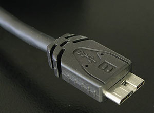
USB 3.0 introduced a new Micro-B cable plug, see photo on the right. It consists of a standard USB 1.x/2.0 Micro-B cable plug, with additional 5-pin plug "stacked" on side of it. That way, USB 3.0 Micro-A host connector preserved its backwards compatibility with the USB 1.x/2.0 Micro-B cable plugs.
Pinouts
See also: USB 3.0 Pinouts
USB is a serial bus, using four shielded wires for the USB 2.0 variant: two for power (VBUS and GND), and two for differential data signals(labelled as D+ and D- in pinouts). Non-Return-to-Zero Inverted (NRZI) encoding scheme is used for transferring data, with a sync field to synchronise the host and receiver clocks. D+ and D- signals are transmitted on a twisted pair, providing half-duplex data transfers for USB 2.0.
There are additional wires present in the USB 3.0 variant, consisting of two twisted pairs and providing various improvements, includingfull-duplex data transfers at increased speed.
| Types-usb th1.svg | Standard, Mini, and Micro USB plugs (not to scale). The white areas in these drawings represent hollow spaces. As the plugs are shown here, the USB logo (with optional letter A or B) is on the top of the overmold in all cases. Pin numbering looking into receptacles is mirrored from plugs, such that pin 1 on plug connects to pin 1 on the receptacle. |
| USB 3.0 Micro B plug.PNG | Micro-B USB 3.0 plug Power (VBUS) USB 2.0 differential pair (D−) USB 2.0 differential pair (D+) USB OTG ID for identifying lines GND USB 3.0 signal transmission line (−) USB 3.0 signal transmission line (+) GND USB 3.0 signal receiving line (−) USB 3.0 signal receiving line (+) |
USB 1.x/2.0 standard pinout
| Pin | Name | Cable color | Description |
| 1 | VBUS | Red (or Orange) | +5 V |
| 2 | D− | White (or Gold) | Data − |
| 3 | D+ | Green | Data + |
| 4 | GND | Black (or Blue) | Ground |
USB 1.x/2.0 Mini/Micro pinout
| Pin | Name | Cable color | Description |
| 1 | VBUS | Red | +5 V |
| 2 | D− | White | Data − |
| 3 | D+ | Green | Data + |
| 4 | ID | N/A | Permits distinction of a host connection from device connection: • host: connected to the signal ground • device: not connected |
| 5 | GND | Black | Signal ground |
Proprietary connectors and formats
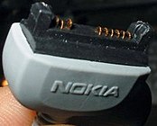
Manufacturers of personal electronic devices might not include a USB standard connector on their product for technical or marketing reasons.Some manufacturers provide proprietary cables that permit their devices to physically connect to a USB standard port. Full functionality of proprietary ports and cables with USB standard ports is not assured; for example, some devices only use the USB connection for battery charging and do not implement any data transfer functions.
Colors
Ports and connectors are often color coded to distinguish different functions. These colors are not part of the USB specification and can vary between manufacturers.
[citation needed]
| Color | Description |
| Black or white | USB 1.x or USB 2.0 |
| Blue | USB 3.0 |
| Yellow or red (ports only) | High current and/or Sleep-and-charge |
